Thursday, September 12, 2013

ISIS Replay script - replay packets from a dump file

As I have shown in an older post, the pyrt isis python module, as I have modified it, does all the work on capturing ISIS packets, parse the packets and save them in a dump file. The pyrt package also contains another useful script, mrtd.py, which can be run separately as it has its' own main function, which provides the necessary code for reading the packets which were saved in a binary format in a dump file and parse them just like in a live capture.

When creating the replay.py script, I have used the code from these pyrt modules to parse the packets from a given dump file and replay them - that is send it back to the given layer 2 address - which can be the multicast address for level 1 ISIS routers, the multicast layer 2 address for level 2 ISIS routers, or an unicast address (by default, the original source address becomes destination address). So basicaly, what I have done is :

1. read all the packages from the dump file
2. take each package which matches the filter - there can be multiple filters - the message type (the default message type to be replayed is the CSNP packets, which contain the necessary information to recreate the topology from scratch), the area-id, etc - and another filters can be easily added.
3. send the package back on a multicast address or to an unicast address

here is how the help option now shows when I run ./replay.py -h (or --help):

gabi@gsoc13:~/isis_tool/isis$ ./replay.py --help
Usage: replay.py [ options ]:
        -h|--help      : Help
        -v|--verbose   : Be verbose
        -t|--type      : ISIS Message type
              0:  "NULL",
              2:  "ESH",
              4:  "ISH",
              6:  "RD",
              15: "L1LANHello",
              16: "L2LANHello",
              17: "PPHello",
              18: "L1LSP",
              20: "L2LSP",
              24: "L1CSN",
              25: "L2CSN",
              26: "L1PSN",
              27: "L2PSN",
        -a|--area-addr  : set the area address to which this IS belongs
        --device        : Set the device to send on the replayed packets
        -f|--file      : Set file name to parse (def: mrtd.mrtd)

Let's try replay-ing the CSNP packets found in a dump file. 
This is the most basic way the script can be called:

sudo ./replay.py -f mrtd.mrtd.2013-07-31_21.45.16 -t 24

the "-t 24" filter is optional in the case for csnp packets, since this is the default message type which the script is set to run.

While the script runs and matches the csnp packets from the dump file, I run separately a tcpdump on the eth0 device (the default one, on which the packets are retransmitted). This is how the results look in wireshark, when running"

 gabi@gsoc13:~$ sudo tcpdump -i eth0 -s 0 -w capture_file isis
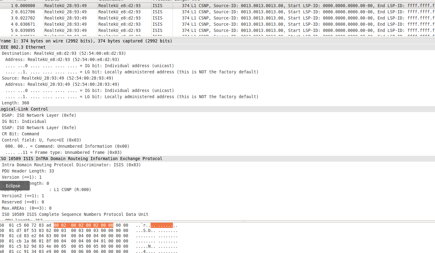

Currently, I am working on allowing more filters to be added, and to check whether the actual packets which are read from the dump file came from a remote router or from another local interface.

Sunday, September 8, 2013

IS-IS replay tool IPv6 support

I added the IPv6 support to the sniffing tool. The IPv6 messages appear inside the HELLO messages.
In the example below, both IPv4 and IPv6 protocols are supported and parsed:

L1LANHello (len=1500):
    src mac: 00.0c.29.f4.67.aa, dst mac: 01.80.c2.00.00.14
    len: 1500, LLC: 0xfe.fe.03
    hdr_len: 27, protocol id: 1, version: 1, eco: 0, user eco: 0
    circuit type: L1Circuit, holdtimer: 50, PDU len: 1497, priority: 64
    src id: 11.11.11.11.11.11, LAN id: 11.11.11.11.11.11.01
    field: AreaAddress, length: 4
        area addresses: 0x49.00.01,
    field: IIHIISNeighbor, length: 6
        IS Neighbour 1: 00.0c.29.47.e4.a1
    field: ProtoSupported, length: 2
        protocols supported: ['IP', 'IPV6']
    field: IPIfAddr, length: 4
        interface IP addresses: ['192.168.9.131']
    field: IPv6IfAddr, length: 16
        interface IPv6 addresses: ['fe.80.00.00.00.00.00.00.02.0c.29.ff.fe.f4.67.aa']
message len is 1514

Tuesday, September 3, 2013

IS-IS quagga IPv6 configuration

I am going to also support IPv6 in my replay tool for this year's GSoC. In order to better understand how IPv6 works with IS-IS, here are the few changes needed to the IPv4 configuration files:

First router:

! -*- isis -*-

hostname isisd
password foo
enable password foo
log stdout

hostname isisd-router
!  area-password foobar
!  domain-password foobar

interface eth1
 ip router isis Test1
 ipv6 router isis Test1
 isis hello-interval 5
! isis lsp-interval 1000

router isis Test1
  net 49.0001.1111.1111.1111.00
  is-type level-1
  metric-style wide

Second router:

! -*- isis -*-

hostname isisd
password foo
enable password foo
log stdout

hostname isisd-router
!  area-password foobar
!  domain-password foobar

interface eth1
 ip router isis Test1
 ipv6 router isis Test1
 isis hello-interval 5

router isis Test1
  net 49.0001.2222.2222.2222.00
  is-type level-1
  metric-style wide

The two files will support both IPv4 and IPv6, if you want only one of them to be supported, simply comment one of the ip or ipv6 lines.

The two routers need to be able to 'see' each other:

ping6 -I eth1 fe80::20c:29ff:fef4:67aa
PING fe80::20c:29ff:fef4:67aa(fe80::20c:29ff:fef4:67aa) from fe80::20c:29ff:fe47:e4a1 eth1: 56 data bytes
64 bytes from fe80::20c:29ff:fef4:67aa: icmp_seq=1 ttl=64 time=1.95 ms
64 bytes from fe80::20c:29ff:fef4:67aa: icmp_seq=2 ttl=64 time=0.246 ms
64 bytes from fe80::20c:29ff:fef4:67aa: icmp_seq=3 ttl=64 time=0.299 ms

Here are the wireshark captures with the IPv6 packets. They appear in the HELLO messages.


Wednesday, July 31, 2013

ISIS replay tool - sniffer stage

Since my last post, I have modified the code from the python routing toolkit to use the python-pypcap library, in order to catch all the ISIS packets (both outgoing and incoming ISIS packets on a given physical interface).

That means that at this stage, the tool can both capture the ISIS packets, interpret all the necessary fields from the ISIS headers and the containing TLVs, similar to how tcpdump and wireshark intepret packets for common protocols. Also, these packets can be stored now in two formats, both the toolkit's specific format and as a simple libpcap capture. Both these formats can be used in both ways - to write the dump and to read it, and interpret it from there.

Also, I have tested this on the GSoC testbed, with the below topology.


Below I have attached printscreens with hello packets and CSNP packets:


And CSNP packets, with the pyrt format on the upper side and the tcpdump equivalent below:


Thursday, July 25, 2013

Python Routing Toolkit - Setup

A very interesting tool to capture, save and parse routing packets for BGPv4, IS-IS and OSPF protocols, I found to be PyRT. For the purpose of my GSoC project I will setup and run the toolkit for IS-IS protocol.

Prerequisites: Python 2.5 (so far, the code hasn't been updated to the latest version of Python).
So first of all I got the right version installed on the virtual machine:
  1. wget http://www.python.org/ftp/python/2.5/Python-2.5.tgz
  2. tar -xvf Python-2.5.tgz  (to extract the files)
  3. cd Python-2.5
  4. sudo ./configure
  5. make
  6. make install
  7. which python2.5 --> /usr/local/bin/python2.5 (to verify that it has been installed correctly in the environment path)
After this, get the pyrt code:
  1. git clone https://github.com/mor1/pyrt.git
  2. sudo python isis.py -d -a 49.00.01 -z $((1024*1024*5)) -f isis-dump -i 192.168.9.129
To run the code you need to set all the parameters as above, with the meaning:

python isis.py
Usage: isis.py [ options ] where options are ([*] required):
        -h|--help       : Help
        -v|--verbose    : Be verbose
        -q|--quiet      : Be quiet
       
        -a|--area-addr  : set the area address to which this IS belongs
        -i|--ip-addr    : *** HACK *** set the IP address to advertise
        -s|--src-id     : set the source ID of this IS
        -l|--lan-id     : set the LAN ID of this IS (def: "<srcid>:01")

        --device        : Set the device to receive on (def: eth0)

        -d|--dump       : Dump MRTd::PROTOCOL_ISIS format
        -y|--dump-isis2 : Dump MRTd::PROTOCOL_ISIS2 format
        -f|--file       : Set file prefix for MRTd dump (def: mrtd.mrtd)
        -z|--size       : Size of output file(s) (min: 51200)

And the output is:

L1LANHello (len=1500):
    src mac: 00.0c.29.47.e4.a1, dst mac: 01.80.c2.00.00.14
    len: 1500, LLC: 0xfe.fe.03
    hdr_len: 27, protocol id: 1, version: 1, eco: 0, user eco: 0
    circuit type: L1Circuit, holdtimer: 50, PDU len: 1497, priority: 64
    src id: 22.22.22.22.22.22, LAN id: 11.11.11.11.11.11.82
    field: AreaAddress, length: 4
        area addresses: 0x49.00.01,
    field: IIHIISNeighbor, length: 6
        IS Neighbour 1: 00.50.56.29.0b.88
    field: ProtoSupported, length: 1
        protocols supported: ['IP']
    field: IPIfAddr, length: 4
        interface IP addresses: ['192.168.9.129']

The packets are stored in a file called:
isis-dump.2013-07-25_08.47.39, which is a .mrtd format file and can be later used to manipulate the data.


Sunday, July 21, 2013

Quagga IS-IS configuration - part 2

I will discuss here how to configure two routers, running on two separate virtual machines (Ubuntu 12.04, installed on vmware player, in my case), to form a simple isis adjacency. The two virtual machines are configured to run on the NAT provided by vmware, with 192.168.x.x/16 addresses. Since the is-is is running over IPv4, it is necessary to have an adjacency at IP level.

First of all, here is a simple configuration file for each of the routers :

! -*- isis -*-
!
! ISISd sample configuration file
!
hostname isisd 
password foo
enable password foo
log stdout 

interface eth0
ip router isis Test1
isis hello-interval 5
! isis lsp-interval 1000

! -- optional
isis circuit-type level-1
! isis password lallaa level-1 
! isis metric 1 level-1
! isis csnp-interval 5 level-1
! isis retransmit-interval 10
! isis retransmit-throttle-interval
! isis hello-multiplier 2 level-1
! isis priority 64

router isis Test1
net 49.0001.1111.1111.1111.00
is-type level-1
metric-style wide

For the other router, the NSAP address should be changed to use another system id, but the same area id, for example: 49.0001.2222.2222.2222.00

Before starting the router daemon, zebra needs to be started. Zebra is the underlying routing suite which allows is-is and the other protocols to send/receive routing packets via de physical interfaces of the systems.
Before starting zebra, the configuration file needs to be created similar to the method used for is-is:
# sudo cp /usr/local/quagga/zebra.conf.sample /usr/local/quagga/zebra.conf
Now, zebra can be started, followed by the isis daemon
# sudo zebra -d
# sudo isisd -d
After the first router is started, you can see hello packets being broadcast using the multicast address:


Also, after starting the second router, you can see broadcast packets coming from the second router:


Finally, after the adjacency is formed, the router 1 has an updated database and sends a CSNP packets to all the Layer-1 routers. The complete sequence number PDU (CSNP) lists all the link-state PDUs (LSPs) in the link-state database of the local router:


Also, by using the vty of the router, you can examine information of the running protocol. In this figure, I will run the command which shows the isis neighbors:


As you can see, the router Test1 has a new formed adjacency with the second router, with the SNPA 000c.2967.c374, which is the mac address of the physical interface of the Test2 router, used for transmiting the isis packets back to Test1.


Thursday, July 11, 2013

IS-IS Overview

Intermediate System to Intermediate System (IS-IS) is a an inter-domain (also called interior gateway) routing protocol, similar to OSPF in the sense that it is also a link-state routing protocol and it uses the Dijkstra algorithm to create the network topology.

However, while OSPF is based on the TCP/IP stack and it works only over ip (and ipv6 since OSPFv3), IS-IS is a more versatile protocol which can also work with IP, but it is essentially designed for the OSI layer, to work as a network layer protocol, on the same layer as CLNS (connectionless-mode network service).


Other similarities with OSPF include - use of hello multicast packets to discover neighboring routers, support for VLSM and CIDR, authentication and multi-path. 


IS-IS levels


  • ISIS does not have a backbone area as such (like OSPF). Instead the backbone is the contiguous collection of Level-2 capable routers with branches of Level 1-2 and Level 1 routers forming the individual areas.
  • ISIS area borders are on links, not routers
  • the routers can be classified as:
    • Level-1 router : 
      • Has neighbours only on the same area
      • Has a level-1 LSDB with all routing information for the area
    • Level-2 router:
      • May have neighbours in the same or other areas
      • Has a Level-2 LSDB with all routing information about inter-area
    • Level-1-2 router:
      • May have neighbours on any area.
      • Has two separate LSDBs: level-1 LSDB & level-2 LSDB
Each router is identified with a unique Network Entity Title (NET). NET is a Network Service Access Point (NSAP) where the n-selector is 0, and then compare with each router having a unique Router-ID with IP protocols.

NSAP
  • Length between 8 and 20 bytes 
  • Area address can have up to 13 bytes
  • System ID defines an IS or an ES in an area
  • NSEL (n-selector) identifies a network service user; transport entity or the IS network entity itself

ISPs usually use only one area, because it is enough to cover a few hundred routers network.
NET address begins with 49, for "private" address range. So, the first 8 bits are usually 49, next 16 bits are the area number, next 48 represent the router loopback address and the rest of the 8 bits are set to 0.

So, an NSAP address commonly looks like: 
49.0001.1921.6800.1001.00, with 192.168.1.1 as loopback address in area 1.


Types of packets


IS-IS Hello PDU

IS-IS hello PDUs, also called Intermediate System-to-Intermediate System Hello (IIH) are used to detect neighbors and establish adjacencies with other routers.
There are three different formats: one for point-to-point hello packets, one for Level 1 broadcast links, and one for Level 2 broadcast links. Level 1 routers must share the same area address to form an adjacency, while Level 2 routers do not have this limitation. The request for adjacency is encoded in the Circuit type field of the PDU.

Link-State PDU

A link-state PDU (LSP) contains information about each router in the network and the connected interfaces. Also included is metric and IS-IS neighbor information. Each LSP must be refreshed periodically on the network and is acknowledged by information within a sequence number packet.
On point-to-point links, each LSP is acknowledged by a partial sequence number PDU (PSNP), but on broadcast links, a complete sequence number PDU (CSNP) is sent out over the network. Any router that finds newer LSP information in the CSNP must delete the out-of-date entry and update the link-state database.
A change in the topology means a change in one or more of the LSPs. The router that has experienced a link going up or down will resend its LSP to inform the other routers of the change.

Flooding is the process by which these new LSPs are sent throughout the network to ensure that the databases in all routers remain identical.

Complete Sequence Number PDU

The complete sequence number PDU (CSNP) lists all the link-state PDUs (LSPs) in the link-state database of the local router. Contained within the CSNP is an LSP identifier, a lifetime, a sequence number, and a checksum for each entry in the database. Periodically, a CSNP is sent on both broadcast and point-to-point links to maintain a correct database. Also, the advertisement of CSNPs occurs when an adjacency is formed with another router. Like IS-IS hello PDUs, CSNPs come in two types: Level 1 and Level 2.
When a device receives a CSNP, it checks the database entries again its own local link-state database. If it detects missing information, the device requests specific LSP details using a partial sequence number PDU (PSNP).

Partial Sequence Number PDU

A partial sequence number PDU (PSNP) is used by an IS-IS router to request LSP information from a neighboring router. A PSNP can also explicitly acknowledge the receipt of an LSP on a point-to-point link. On a broadcast link, a CSNP is used as implicit knowledge. Like hello PDUs and CSNPs, the PSNP also has two types: Level 1 and Level 2.

When a device compares a CSNP to its local database and determines that an LSP is missing, the router issues a PSNP for the missing LSP, which is returned in a link-state PDU from the router sending the CSNP. The received LSP is then stored in the local database, and an acknowledgement is sent back to the originating router.


Network Types 

The types of networks that IS-IS defines include:
•Point-to-point networks
•Broadcast networks

Point-to-point networks, such as serial lines, connect a single pair of routers. A router running IS-IS will form an adjacency with the neighbor on the other side of a point-to-point interface. A DIS is not elected on this type of link. The basic mechanism defined in the standard is that each side of the link declares the other side to be reachable if a hello packet is received from it. When this occurs, each side then sends a CSNP to trigger database synchronization.

Broadcast networks, such as Ethernet, are multiaccess in that they are able to connect more than two devices; all connected routers will receive a packet sent by one router. On broadcast networks, one IS will elect itself the DIS. Hello packets on broadcast networks are sent to the AllL1ISs or AllL2ISs MAC-layer broadcast addresses. The DIS is responsible for flooding;

Saturday, July 6, 2013

Quagga - installation and configuration

Installation and configuration steps:

Prerequisites:
Before configuring and installing quagga, the following packages need to be installed first:
awk (gawk works fine)
libzebra (or libidzebra)
libreadline6-dev (version 5 should work as well)
libreadline6 (version 5 should work as well)

After installing this libraries, you should run sudo ldconfig just to be sure to refresh the library path.

First, the default user quagga needs to be created. Another user can be specified to the configure script, but this shows how to configure quagga with the default user:

[root@fedora ~]# adduser quagga
[root@fedora ~]# mkdir /usr/local/quagga
[root@fedora ~]# chown quagga:quagga /usr/local/quagga

After this, you need to call the ./configure script:
[root@fedora ~]# cd /usr/local/src/quagga-0.99.11/
[root@fedora quagga-0.99.11]# ./configure --sysconfdir=/usr/local/quagga --localstatedir=/usr/local/quagga

If some of the implemented protocols aren't needed, they can be disabled. Also, isis has to be enabled manually:

[root@fedora quagga-0.99.11]# ./configure --enable-isisd --disable-ripd \
>   --disable-ripngd --disable-ospfd --disable-ospf6d \
>   --sysconfdir=/usr/local/quagga --localstatedir=/usr/local/quagga

If you want to use isis,
Next:
[root@fedora quagga-0.99.11]# ./make
[root@fedora quagga-0.99.11]# ./make install

You will notice that the installation script has created sample config files for each deamon in the /usr/local/quagga folder. In order to work, you need to create conf files both in /usr/local/etc and in /usr/local/quagga. The config file in use will be the one in the directory set at configure time, in our case /usr/local/quagga.

Example for isisd:

[root@fedora quagga-0.99.11]# sudo cp /usr/local/quagga/isisd.conf.sample /usr/local/quagga/isisd.conf
[root@fedora quagga-0.99.11]# sudo cp /usr/local/quagga/isisd.conf.sample /usr/local/etc/isisd.conf

Now, you can run a daemon by calling:
[root@fedora quagga-0.99.11]# sudo isisd -d
Additional, a script for configuring and installing quagga (an example):
#!/bin/sh

QPATH=~/QUAGGA/quagga-0.99.22
cd $QPATH

case $1 in

    build)
        make distclean
     ./configure --enable-isisd --disable-ripngd --disable-ospf6d --sysconfdir=/usr/local/quagga --localstatedir=/usr/local/quagga --enable-vtysh
 make
 ;;

    install)
     make install
 ;;

    clean)
     make clean

esac

Thursday, July 7, 2011

BSD improve IPv6

Some continuation to the previous post:

Ping from host with code using mac addresses for gw (ipv6 addr fd00::3/128):
fd00::1 (linux host)
ping6 fd00::1
PING6(56=40+8+8 bytes) fd00::3 --> fd00::1
16 bytes from fd00::1, icmp_seq=0 hlim=64 time=4.047 ms
16 bytes from fd00::1, icmp_seq=1 hlim=64 time=1.792 ms
16 bytes from fd00::1, icmp_seq=2 hlim=64 time=0.795 ms
^C
--- fd00::1 ping6 statistics ---
3 packets transmitted, 3 packets received, 0.0% packet loss
round-trip min/avg/max/std-dev = 0.795/2.211/4.047/1.360 ms

fd00::4 (freebsd host running original code)
ping6 fd00::4
PING6(56=40+8+8 bytes) fd00::3 --> fd00::4
no response

tcpdump -nei re0 output on host with original code:
10:07:21.720560 00:01:00:00:00:04 > 33:33:00:00:00:6d, ethertype IPv6 (0x86dd), length 158: fd00::4.698 > ff02::6d.698: OLSR, seq 0xd218, length 96
10:07:21.909741 00:01:00:00:00:04 > 02:21:30:ca:dd:35, ethertype IPv4 (0x0800), length 114: 10.0.0.4.22 > 10.0.0.99.36085: Flags [P.], ack 49, win 8326, options [nop,nop,TS val 1136371185 ecr 2080490], length 48
10:07:21.910094 02:21:30:ca:dd:35 > 00:01:00:00:00:04, ethertype IPv4 (0x0800), length 66: 10.0.0.99.36085 > 10.0.0.4.22: Flags [.], ack 35472, win 1002, options [nop,nop,TS val 2080648 ecr 1136371185], length 0
10:07:21.974657 00:01:00:00:00:03 > 33:33:ff:00:00:04, ethertype IPv6 (0x86dd), length 86: fd00::3 > ff02::1:ff00:4: ICMP6, neighbor solicitation, who has fd00::4, length 32
10:07:22.014421 00:01:00:00:00:04 > 33:33:ff:00:00:03, ethertype IPv6 (0x86dd), length 86: fd00::4 > ff02::1:ff00:3: ICMP6, neighbor solicitation, who has fe80::3, length 32

So the original code, doesn't know where to send the answer for the ICMP request, that's why the other host doesn't receive anything.

Also, I tested and the code using lonklocal address, but adds only a default route works the same as the one using mac addresse, but I'm nt sure if it is the best.

Wednesday, July 6, 2011

Improve olsrd on BSD: use linklocal address or not?

Olsrd before the improvements (no filtering, each node can see all others):
IPv4:

--- 20:53:00.042579 ---------------------------------------------------- LINKS

IP address       hyst         LQ       ETX
10.0.0.3         0.000  1.000/1.000    1.000
10.0.0.2         0.000  0.839/0.761    1.565
10.0.0.1         0.000  1.000/1.000    1.000

--- 20:53:03.216848 ----------------------- TWO-HOP NEIGHBORS

IP addr (2-hop)  IP addr (1-hop)  Total cost
10.0.0.3         10.0.0.1         2.000
                 10.0.0.2         3.117
10.0.0.1         10.0.0.2         3.582
                 10.0.0.3         2.000
10.0.0.2         10.0.0.3         2.128
                 10.0.0.1         2.595

netstat output:

netstat -rn
Routing tables

Internet:
Destination        Gateway            Flags    Refs      Use  Netif Expire
10.0.0.0/8         link#1             U           2    13258    re0
10.0.0.1/32        00:01:00:00:00:04  U           0        0    re0
10.0.0.2           10.0.0.3           UGH         0        5    re0 =>
10.0.0.2/32        00:01:00:00:00:04  U           0        0    re0
10.0.0.3           10.0.0.2           UGH         0        2    re0 =>
10.0.0.3/32        00:01:00:00:00:04  U           0        0    re0
10.0.0.4           link#1             UHS         0        0    lo0
127.0.0.1          link#4             UH          0        0    lo0

Aliases are also created and not deleted after closing olsrd.


IPv6:
--- 21:18:09.197225 ---------------------------------------------------- LINKS

IP address                               hyst         LQ       ETX
fd00::1                                  0.000  1.000/1.000    1.000
fd00::2                                  0.000  1.000/1.000    1.000
fd00::3                                  0.000  1.000/1.000    1.000

--- 21:18:09.197602 ----------------------- TWO-HOP NEIGHBORS

IP addr (2-hop)  IP addr (1-hop)  Total cost
fd00::3          fd00::2          2.000
                 fd00::1          2.000
fd00::1          fd00::3          2.000
                 fd00::2          2.000
fd00::2          fd00::3          2.000
                 fd00::1          2.000


netstat output:
Internet6:
Destination                       Gateway                       Flags      Netif Expire
::/96                             ::1                           UGRS        lo0
::1                               ::1                           UH          lo0
::ffff:0.0.0.0/96                 ::1                           UGRS        lo0
fd00::/8                          link#1                        U           re0
fd00::1                           fe80::1%re0                   UGH         re0
fd00::2                           fe80::2%re0                   UGH         re0
fd00::3                           fe80::3%re0                   UGH         re0
fd00::4                           link#1                        UHS         lo0
fe80::/10                         ::1                           UGRS        lo0
fe80::%re0/64                     link#1                        U           re0
fe80::201:ff:fe00:4%re0           link#1                        UHS         lo0
fe80::%re1/64                     link#2                        U           re1
fe80::201:ff:fe00:d%re1           link#2                        UHS         lo0
fe80::%lo0/64                     link#4                        U           lo0
fe80::1%lo0                       link#4                        UHS         lo0
ff01:1::/32                       fe80::201:ff:fe00:4%re0       U           re0
ff01:2::/32                       fe80::201:ff:fe00:d%re1       U           re1
ff01:4::/32                       ::1                           U           lo0
ff02::/16                         ::1                           UGRS        lo0
ff02::%re0/32                     fe80::201:ff:fe00:4%re0       U           re0
ff02::%re1/32                     fe80::201:ff:fe00:d%re1       U           re1
ff02::%lo0/32                     ::1                           U           lo0


Olsrd with no aliases added:
IPv4:
netstat output:

netstat -rn
Routing tables

Internet:
Destination        Gateway            Flags    Refs      Use  Netif Expire
10.0.0.0/8         link#1             U           2     8707    re0
10.0.0.1/32        00:01:00:00:00:03  U           0        0    re0
10.0.0.2/32        00:01:00:00:00:03  U           0       11    re0
10.0.0.3           link#1             UHS         0        0    lo0
10.0.0.4/32        00:01:00:00:00:03  U           0        0    re0
127.0.0.1          link#4             UH          0        0    lo0

IPv6:
netstat output:

Internet6:
Destination                       Gateway                       Flags      Netif Expire
::/96                             ::1                           UGRS        lo0 =>
default                           fe80::4%re0                   U           re0
::1                               ::1                           UH          lo0
::ffff:0.0.0.0/96                 ::1                           UGRS        lo0
fd00::/8                          link#1                        U           re0
fd00::3                           link#1                        UHS         lo0
fe80::/10                         ::1                           UGRS        lo0
fe80::%re0/64                     link#1                        U           re0
fe80::201:ff:fe00:3%re0           link#1                        UHS         lo0
fe80::%lo0/64                     link#4                        U           lo0
fe80::1%lo0                       link#4                        UHS         lo0
ff01:1::/32                       fe80::201:ff:fe00:3%re0       U           re0
ff01:4::/32                       ::1                           U           lo0
ff02::/16                         ::1                           UGRS        lo0
ff02::%re0/32                     fe80::201:ff:fe00:3%re0       U           re0
ff02::%lo0/32                     ::1                           U           lo0


So, instead of routes, there is only one default route created, which is not deleted after closing olsrd.

Olsrd with no aliases, and MAC addresses for IPv6 gateways:
IPv4:
netstat output:
netstat -rn
Routing tables

Internet:
Destination        Gateway            Flags    Refs      Use  Netif Expire
10.0.0.0/8         link#1             U           2    20770    re0
10.0.0.1/32        00:01:00:00:00:03  U           0        0    re0
10.0.0.2/32        00:01:00:00:00:03  U           0        0    re0
10.0.0.3           link#1             UHS         0        0    lo0
10.0.0.4/32        00:01:00:00:00:03  U           0        0    re0
127.0.0.1          link#4             UH          0        0    lo0

IPv6:
netstat output:
Internet6:
Destination                       Gateway                       Flags      Netif Expire
::/96                             ::1                           UGRS        lo0
::1                               ::1                           UH          lo0
::ffff:0.0.0.0/96                 ::1                           UGRS        lo0
fd00::/8                          link#1                        U           re0
fd00::1/128                       00:01:00:00:00:03             U           re0
fd00::2/128                       00:01:00:00:00:03             U           re0
fd00::3                           link#1                        UHS         lo0
fd00::4/128                       00:01:00:00:00:03             U           re0
fe80::/10                         ::1                           UGRS        lo0
fe80::%re0/64                     link#1                        U           re0
fe80::201:ff:fe00:3%re0           link#1                        UHS         lo0
fe80::%lo0/64                     link#4                        U           lo0
fe80::1%lo0                       link#4                        UHS         lo0
ff01:1::/32                       fe80::201:ff:fe00:3%re0       U           re0
ff01:4::/32                       ::1                           U           lo0
ff02::/16                         ::1                           UGRS        lo0
ff02::%re0/32                     fe80::201:ff:fe00:3%re0       U           re0
ff02::%lo0/32                     ::1                           U           lo0

Thursday, June 30, 2011

Strange olsrd behaviour running on 2 FreeBSD vms

So, the same code, same exec file, same config file for both vms running IPv6 mode; I used scp to be sure I have the same thing on both.
No packetloss script used, so I get more routes for one destination.
The output for the first one (used the most for testing):


Nothing wrong so far, but the netstat -rn output looks like this:

Internet6:
Destination                       Gateway                       Flags      Netif Expire
::1                                      ::1                                 UH          lo0
fd00::/8                             link#1                           U             re0
fd00::3                              link#1                           UHS        lo0
fe80::%lo0/64                   link#4                           U             lo0
fe80::1%lo0                      link#4                           UHS        lo0
ff01:1::/32                        fd00::3                           U             re0
ff01:4::/32                        fe80::1%lo0                   U             lo0
ff02::%re0/32                   fd00::3                          U             re0
ff02::%lo0/32                   fe80::1%lo0                   U            lo0

re0 is the interface on which olsrd runs.
No IPv6 route added to the kernel routing table.

The output for the second vm:


The output for netstat -rn for this vm is:

Internet6:
Destination                       Gateway                       Flags      Netif Expire
::/96                                    ::1                                 UGRS        lo0
::1                                       ::1                                 UH            lo0
::ffff:0.0.0.0/96                   ::1                                 UGRS        lo0
fd00::/8                              link#1                           U               re0
fd00::1/0                            fe80::1%re0                  U               re0
fd00::2/0                            fe80::2%re0                  U               re0
fd00::3/0                            fe80::3%re0                  U               re0
fd00::4                               link#1                           UHS          lo0
fe80::/10                            ::1                                 UGRS         lo0
fe80::%re0/64                    link#1                          U                re0
fe80::201:ff:fe00:4%re0     link#1                          UHS          lo0
fe80::%re1/64                    link#2                          U                re1
fe80::201:ff:fe00:d%re1     link#2                          UHS          lo0
fe80::%lo0/64                     link#4                          U               lo0
fe80::1%lo0                        link#4                          UHS          lo0
ff01:1::/32                        fe80::201:ff:fe00:4%re0   U             re0
ff01:2::/32                        fe80::201:ff:fe00:d%re1   U             re1
ff01:4::/32                         ::1                                  U              lo0
ff02::/16                            ::1                                  UGRS       lo0
ff02::%re0/32                  fe80::201:ff:fe00:4%re0    U            re0
ff02::%re1/32                  fe80::201:ff:fe00:d%re1    U            re1
ff02::%lo0/32                    ::1                                  U              lo0

So, you can see the output is very different, this one is better, but not the best.

Sunday, June 26, 2011

FreeBSD vm configure

Since I had some trouble in configuring the FreeBSD vm, here are some basic steps into making a vm work for development:
1. install a package using
pkg_add -r {pkg-name}
portsnap fetch update - similar to apt-get update
portsnap extract
portsnap update
2. enable root ssh login:
edit /etc/ssh/sshd_config by adding PermitRootLogin option, and running /etc/rc.d/sshd reload to activate the change;
3. adding ipv6 net address using
# ifconfig {interface-name} inet6 {IPv6-Address} prefixlen {routed-bit}
4. for internet access configure dns, in /etc/resolv.conf, and gateway to be the same as for your host;
route add default {gw_ip_addr}
5. to run olsrd, the olsrd.conf must be edited and copied into /usr/local/etc;

Wednesday, May 18, 2011

Topology routing table view

On 10.0.0.1:

Table: Links
Local IP    Remote IP    Hyst.    LQ    NLQ    Cost
10.0.0.1    10.0.0.3    0.00    1.000    1.000    1.000   

Table: Neighbors
IP address    SYM    MPR    MPRS    Will.    2 Hop Neighbors
10.0.0.3    YES    YES    NO    3    3

Table: Topology
Dest. IP    Last hop IP    LQ    NLQ    Cost
10.0.0.3    10.0.0.1    1.000    1.000    1.000
10.0.0.3    10.0.0.2    1.000    1.000    1.000
10.0.0.1    10.0.0.3    1.000    1.000    1.000
10.0.0.2    10.0.0.3    1.000    1.000    1.000
10.0.0.4    10.0.0.3    1.000    1.000    1.000
10.0.0.5    10.0.0.3    1.000    1.000    1.000
10.0.0.3    10.0.0.4    1.000    1.000    1.000
10.0.0.3    10.0.0.5    1.000    1.000    1.000

Table: HNA
Destination    Gateway

Table: MID
IP address    Aliases

Table: Routes
Destination    Gateway IP    Metric    ETX    Interface
10.0.0.2/32    10.0.0.3    2    2.000    if02   
10.0.0.3/32    10.0.0.3    1    1.000    if02   
10.0.0.4/32    10.0.0.3    2    2.000    if02   
10.0.0.5/32    10.0.0.3    2    2.000    if02   

On 10.0.0.2:
Table: Links
Local IP    Remote IP    Hyst.    LQ    NLQ    Cost
10.0.0.2    10.0.0.3    0.00    1.000    1.000    1.000   

Table: Neighbors
IP address    SYM    MPR    MPRS    Will.    2 Hop Neighbors
10.0.0.3    YES    YES    NO    3    3

Table: Topology
Dest. IP    Last hop IP    LQ    NLQ    Cost
10.0.0.3    10.0.0.1    1.000    1.000    1.000
10.0.0.3    10.0.0.2    1.000    1.000    1.000
10.0.0.1    10.0.0.3    1.000    1.000    1.000
10.0.0.2    10.0.0.3    1.000    1.000    1.000
10.0.0.4    10.0.0.3    1.000    1.000    1.000
10.0.0.5    10.0.0.3    1.000    1.000    1.000
10.0.0.3    10.0.0.4    1.000    1.000    1.000
10.0.0.3    10.0.0.5    1.000    1.000    1.000

Table: HNA
Destination    Gateway

Table: MID
IP address    Aliases

Table: Routes
Destination    Gateway IP    Metric    ETX    Interface
10.0.0.1/32    10.0.0.3    2    2.000    if02   
10.0.0.3/32    10.0.0.3    1    1.000    if02   
10.0.0.4/32    10.0.0.3    2    2.000    if02   
10.0.0.5/32    10.0.0.3    2    2.000    if02   

On 10.0.0.3:
Table: Links
Local IP    Remote IP    Hyst.    LQ    NLQ    Cost
10.0.0.3    10.0.0.5    0.00    1.000    1.000    1.000   
10.0.0.3    10.0.0.1    0.00    1.000    1.000    1.000   
10.0.0.3    10.0.0.2    0.00    1.000    1.000    1.000   
10.0.0.3    10.0.0.4    0.00    1.000    1.000    1.000   

Table: Neighbors
IP address    SYM    MPR    MPRS    Will.    2 Hop Neighbors
10.0.0.4    YES    NO    YES    3    0
10.0.0.5    YES    NO    YES    3    0
10.0.0.1    YES    NO    YES    3    0
10.0.0.2    YES    NO    YES    3    0

Table: Topology
Dest. IP    Last hop IP    LQ    NLQ    Cost
10.0.0.3    10.0.0.1    1.000    1.000    1.000
10.0.0.3    10.0.0.2    1.000    1.000    1.000
10.0.0.1    10.0.0.3    1.000    1.000    1.000
10.0.0.2    10.0.0.3    1.000    1.000    1.000
10.0.0.4    10.0.0.3    1.000    1.000    1.000
10.0.0.5    10.0.0.3    1.000    1.000    1.000
10.0.0.3    10.0.0.4    1.000    1.000    1.000
10.0.0.3    10.0.0.5    1.000    1.000    1.000

Table: HNA
Destination    Gateway

Table: MID
IP address    Aliases

Table: Routes
Destination    Gateway IP    Metric    ETX    Interface
10.0.0.1/32    10.0.0.1    1    1.000    if02   
10.0.0.2/32    10.0.0.2    1    1.000    if02   
10.0.0.4/32    10.0.0.4    1    1.000    if02   
10.0.0.5/32    10.0.0.5    1    1.000    if02   

On 10.0.0.4:
Table: Links
Local IP    Remote IP    Hyst.    LQ    NLQ    Cost
10.0.0.4    10.0.0.3    0.00    1.000    1.000    1.000   

Table: Neighbors
IP address    SYM    MPR    MPRS    Will.    2 Hop Neighbors
10.0.0.3    YES    YES    NO    3    3

Table: Topology
Dest. IP    Last hop IP    LQ    NLQ    Cost
10.0.0.3    10.0.0.1    1.000    1.000    1.000
10.0.0.3    10.0.0.2    1.000    1.000    1.000
10.0.0.1    10.0.0.3    1.000    1.000    1.000
10.0.0.2    10.0.0.3    1.000    1.000    1.000
10.0.0.4    10.0.0.3    1.000    1.000    1.000
10.0.0.5    10.0.0.3    1.000    1.000    1.000
10.0.0.3    10.0.0.4    1.000    1.000    1.000
10.0.0.3    10.0.0.5    1.000    1.000    1.000

Table: HNA
Destination    Gateway

Table: MID
IP address    Aliases

Table: Routes
Destination    Gateway IP    Metric    ETX    Interface
10.0.0.1/32    10.0.0.3    2    2.000    if02   
10.0.0.2/32    10.0.0.3    2    2.000    if02   
10.0.0.3/32    10.0.0.3    1    1.000    if02   
10.0.0.5/32    10.0.0.3    2    2.000    if02   

On 10.0.0.5:
Table: Links
Local IP    Remote IP    Hyst.    LQ    NLQ    Cost
10.0.0.5    10.0.0.3    0.00    1.000    1.000    1.000   

Table: Neighbors
IP address    SYM    MPR    MPRS    Will.    2 Hop Neighbors
10.0.0.3    YES    YES    NO    3    3

Table: Topology
Dest. IP    Last hop IP    LQ    NLQ    Cost
10.0.0.3    10.0.0.1    1.000    1.000    1.000
10.0.0.3    10.0.0.2    1.000    1.000    1.000
10.0.0.1    10.0.0.3    1.000    1.000    1.000
10.0.0.2    10.0.0.3    1.000    1.000    1.000
10.0.0.4    10.0.0.3    1.000    1.000    1.000
10.0.0.5    10.0.0.3    1.000    1.000    1.000
10.0.0.3    10.0.0.4    1.000    1.000    1.000
10.0.0.3    10.0.0.5    1.000    1.000    1.000

Table: HNA
Destination    Gateway

Table: MID
IP address    Aliases

Table: Routes
Destination    Gateway IP    Metric    ETX    Interface
10.0.0.1/32    10.0.0.3    2    2.000    if02   
10.0.0.2/32    10.0.0.3    2    2.000    if02   
10.0.0.3/32    10.0.0.3    1    1.000    if02   
10.0.0.4/32    10.0.0.3    2    2.000    if02